A flat plate floor system is a concrete system that has uniform thickness. They are generally cast-in-place or they may be casted at the ground level and lifted into their final position by the use of jacks at the columns. This system can be post-tensioned. Flat plate post tensioned concrete slabs are widely used in office buildings, institutional structures, parking structures, apartment buildings, and hotels. Therefore, it is important to have a good understanding of the behavior of these elements that form the fabric of the total structural system. The main goal of this work was to perform a design evaluation on a constructed scaled post-tensioned 4 ft x 4 ft flat plate concrete slab with American Concrete Institute (ACI) design provisions. The 28 days compressive strength of concrete was 5000 psi. The slab thickness was 1/2 in, and 1/16 in post-tensioning cables inside a plastic sheathing were used as the reinforcement. The slab was loaded using a designed water tank of 4 ft x 4 ft x 6 ft dimensions. The water depth generated the distributed load on the slab and a dial gauge measured the slab deflections. Distributed load and deflection data were collected. The design evaluations were carried out with respect to deflections, stresses, shear and flexural capacity using a developed ACI provisioned spreadsheet and experimentally obtained load and deflection data. The scaled constructed concrete slab satisfied the ACI design provisions.
| Published in | Engineering and Applied Sciences (Volume 10, Issue 5) |
| DOI | 10.11648/j.eas.20251005.11 |
| Page(s) | 114-122 |
| Creative Commons |
This is an Open Access article, distributed under the terms of the Creative Commons Attribution 4.0 International License (http://creativecommons.org/licenses/by/4.0/), which permits unrestricted use, distribution and reproduction in any medium or format, provided the original work is properly cited. |
| Copyright |
Copyright © The Author(s), 2025. Published by Science Publishing Group |
Load, Scaled, Post-Tensioned, Flat Plate, Concrete
Physical Properties | Coarse Aggregates | Fine Aggregates |
|---|---|---|
Sieve Analysis | Passing sieve No.4 (3/16 in) and retained on sieve No.16 (3/64 in) | Passing sieve No.16 (3/64 in) |
Unit Weight (dry) | 98.61 lb/ft3 | 95.02 lb/ft3 |
Unit Weight (ssd) | 100.20 lb/ft3 | 103.53 lb/ft3 |
Absorption | 1.61% | 8.96% |
Specific Gravity | 2.55 | 2.49 |
Fineness Modulus | ------ | 2.50 |
Cylinder No. | Compression Force (lb) |
1 | 40,559 |
2 | 35,694 |
3 | 31,957 (Controls) |
Cylinder No. | Compression Force (lb) |
1 | 42,161 |
2 | 43,842 |
3 | 37,790 (Controls) |
Cylinder No. | Compression Force (lb) |
1 | 53,650 |
2 | 50,605 |
3 | 52,009 (Controls) |
Cable # | Ultimate load capacity (lb) | Observation |
|---|---|---|
1 | 336.19 | Sliding in anchor. It was not properly tightened |
2 | 514.16 | No failure at the anchor |
3 | 553.72 | No failure at the anchor |
4 | 533.94 | No failure at the anchor |
Depth of water (ft) | Distributed load (lb/ft2) | Weight (lb) | Dial gauge reading (inches / 1000) | Observations |
|---|---|---|---|---|
0.00 | 0 | 0 | 0.00 | No leaks, no visible cracks |
0.25 | 16 | 212 | 0.00 | |
0.50 | 31 | 423 | 0.00 | No leaks, no visible cracks |
0.75 | 47 | 635 | 0.50 | |
1.00 | 62 | 847 | 1.25 | No leaks, no visible cracks |
1.25 | 78 | 1058 | 3.00 | |
1.50 | 94 | 1270 | 4.00 | No leaks, no visible cracks |
1.75 | 109 | 1482 | 5.00 | |
2.00 | 125 | 1694 | 5.25 | No leaks, no visible cracks |
2.25 | 140 | 1905 | 5.50 | |
2.50 | 156 | 2117 | 5.75 | No leaks, no visible cracks |
2.75 | 172 | 2329 | 6.00 | |
3.00 | 187 | 2540 | 6.00 | No leaks, no visible cracks |
3.25 | 203 | 2752 | 7.50 | |
3.50 | 218 | 2964 | 8.00 | No leaks, no visible cracks |
3.75 | 234 | 3175 | 9.00 | |
4.00 | 250 | 3387 | 9.50 | No leaks, no visible cracks |
4.25 | 265 | 3599 | 11.00 | |
4.50 | 281 | 3810 | 12.25 | No leaks, no visible cracks |
4.75 | 296 | 4022 | 14.00 | |
5.00 | 312 | 4234 | 15.00 | No leaks, no visible cracks |
5.25 | 328 | 4446 | 17.00 |
Depth of water (ft) | Distributed Load (lb/ft2) | Weight (lb) | Deflections | Stresses | Shear and Flexural Capacities | Factor of Safety (Due to live load) |
|---|---|---|---|---|---|---|
0.00 | 0 | 0 | Within ACI limit | Correlate | Correlate | __ |
0.25 | 16 | 212 | Within ACI limit | Correlate | Correlate | __ |
0.50 | 31 | 423 | Within ACI limit | Correlate | Correlate | __ |
0.75 | 47 | 635 | Within ACI limit | Correlate | Correlate | __ |
1.00 | 62 | 847 | Within ACI limit | Correlate | Correlate | 1.00 |
1.25 | 78 | 1058 | Within ACI limit | Correlate | Correlate | 1.3 |
1.50 | 94 | 1270 | Within ACI limit | Correlate | Correlate | 1.5 |
1.75 | 109 | 1482 | Within ACI limit | Correlate | Correlate | 1.8 |
2.00 | 125 | 1694 | Within ACI limit | Correlate | Correlate | 2.0 |
2.25 | 140 | 1905 | Within ACI limit | Correlate | Correlate | 2.3 |
2.50 | 156 | 2117 | Within ACI limit | Correlate | Correlate | 2.5 |
2.75 | 172 | 2329 | Within ACI limit | Correlate | Correlate | 2.8 |
3.00 | 187 | 2540 | Within ACI limit | Correlate | Correlate | 3.0 |
3.25 | 203 | 2752 | Within ACI limit | Correlate | Correlate | 3.3 |
3.50 | 218 | 2964 | Within ACI limit | Correlate | Correlate | 3.5 |
3.75 | 234 | 3175 | Within ACI limit | Correlate | Correlate | 3.8 |
4.00 | 250 | 3387 | Within ACI limit | Correlate | Correlate | 4.0 |
4.25 | 265 | 3599 | Within ACI limit | Correlate | Correlate | __ |
4.50 | 281 | 3810 | Within ACI limit | Correlate | Correlate | __ |
4.75 | 296 | 4022 | Within ACI limit | Correlate | Correlate | __ |
5.00 | 312 | 4234 | Within ACI limit | Correlate | Correlate | __ |
5.25 | 328 | 4446 | Within ACI limit | Correlate | Correlate | __ |
ssd | Saturated Surface Dry |
f’c | Compressive Strength of Concrete |
fy | Yield Strength of Steel |
fpu | Ultimate Strength of Tendon |
| [1] |
The Constructor, “Flat Plate Floor System-Features and Advantages”. Available from
https://theconstructor.org/building/flat-plate-floor-system-features-advantages/36113/ [Accessed 6 July 2021]. |
| [2] | Mota, Mike., et, (2022), “High-Performance Concrete Flat-Plate Floor System,” Concrete International. |
| [3] |
Buildings, “Concrete Floor-Two-Way, Plate”. Available from
https://www.dimensions.com/element/concrete-floor-two-way-plate [Accessed 3 June 2023]. |
| [4] |
EB3 Construction, “A Deep Dive into Concrete Slab Systems and Construction Best Practices”. Available from
https://blog.eb3construction.com/construction/project-management/slab-construction/ [Accessed 7 July 2025]. |
| [5] | Structures Design Guidelines., (2023), “Structures Manual,” Vol. 1, Florida Department of Transportation. |
| [6] |
Malta Chamber of Construction Management, “Usage of Flat Slab in Construction Industry”. Available from
https://mccm.org.mt/usage-of-flat-slab-in construction industry/ [Accessed 13 September 2023]. |
| [7] |
Housing, “Flat slab: What is it, types advantages and disadvantages”. Available from
https://housing.com/news/flat-slab-why-should-you-build-with-a-flat-slab/ [Accessed 21 August 2025]. |
| [8] |
The Constructor, “Flat Slab-Types of Flat Slab Design and its Advantages”. Available from
https://theconstructor.org/structural-engg/flat-slabtypes-design-advantages/13919/ [Accessed 5 June 2025]. |
| [9] | Hemali, P., (2024), Flat Slab: Types, Advantages, and Design Techniques,” Construction Guide. |
| [10] |
Benchmark Fabricated Steel, “The Advantages of Flat Concrete Slab”. Available from
https://benchmarksteel.com/2023/08/the-advantages-of-flat-plate-concrete-slab/ [Accessed 27 August 2023]. |
| [11] |
Brick and Bolt, “Types of Flat Slab-Benefits and Design Guide in Construction”. Available from
https://www.bricknbolt.com/blogs-and-articles/construction-guide/flat-slab [Accessed 3 March 2025]. |
| [12] | ACI Committee 318, “Building Code Requirements for Structural Concrete (ACI 318-23) and Commentary (ACI 318R-19),” American Concrete Institute, Farmington Hills, MI, 2023, 623 pp. |
| [13] | Standard Specification for Portland Cement., (2024), ASTM C150/C150M-24 American Society of Testing Materials. |
| [14] | Standard Specification for Portland Cement., (2023), ASTM C33/C33M-18 American Society of Testing Materials. |
| [15] | Portland Cement Association., (2021), “Design and Control of Concrete Mixtures,” 17th Edition. |
APA Style
Faruqi, M., Vargas, C. (2025). Diagnostic Load Test of a Scaled Post-Tensioned Flat Plate Concrete Slab. Engineering and Applied Sciences, 10(5), 114-122. https://doi.org/10.11648/j.eas.20251005.11
ACS Style
Faruqi, M.; Vargas, C. Diagnostic Load Test of a Scaled Post-Tensioned Flat Plate Concrete Slab. Eng. Appl. Sci. 2025, 10(5), 114-122. doi: 10.11648/j.eas.20251005.11
AMA Style
Faruqi M, Vargas C. Diagnostic Load Test of a Scaled Post-Tensioned Flat Plate Concrete Slab. Eng Appl Sci. 2025;10(5):114-122. doi: 10.11648/j.eas.20251005.11
@article{10.11648/j.eas.20251005.11,
  author = {Mohammed Faruqi and Carlos Vargas},
  title = {Diagnostic Load Test of a Scaled Post-Tensioned Flat Plate Concrete Slab
},
  journal = {Engineering and Applied Sciences},
  volume = {10},
  number = {5},
  pages = {114-122},
  doi = {10.11648/j.eas.20251005.11},
  url = {https://doi.org/10.11648/j.eas.20251005.11},
  eprint = {https://article.sciencepublishinggroup.com/pdf/10.11648.j.eas.20251005.11},
  abstract = {A flat plate floor system is a concrete system that has uniform thickness. They are generally cast-in-place or they may be casted at the ground level and lifted into their final position by the use of jacks at the columns. This system can be post-tensioned. Flat plate post tensioned concrete slabs are widely used in office buildings, institutional structures, parking structures, apartment buildings, and hotels. Therefore, it is important to have a good understanding of the behavior of these elements that form the fabric of the total structural system. The main goal of this work was to perform a design evaluation on a constructed scaled post-tensioned 4 ft x 4 ft flat plate concrete slab with American Concrete Institute (ACI) design provisions. The 28 days compressive strength of concrete was 5000 psi. The slab thickness was 1/2 in, and 1/16 in post-tensioning cables inside a plastic sheathing were used as the reinforcement. The slab was loaded using a designed water tank of 4 ft x 4 ft x 6 ft dimensions. The water depth generated the distributed load on the slab and a dial gauge measured the slab deflections. Distributed load and deflection data were collected. The design evaluations were carried out with respect to deflections, stresses, shear and flexural capacity using a developed ACI provisioned spreadsheet and experimentally obtained load and deflection data. The scaled constructed concrete slab satisfied the ACI design provisions.
},
 year = {2025}
}
TY  - JOUR
T1  - Diagnostic Load Test of a Scaled Post-Tensioned Flat Plate Concrete Slab

AU  - Mohammed Faruqi
AU  - Carlos Vargas
Y1  - 2025/09/11
PY  - 2025
N1  - https://doi.org/10.11648/j.eas.20251005.11
DO  - 10.11648/j.eas.20251005.11
T2  - Engineering and Applied Sciences
JF  - Engineering and Applied Sciences
JO  - Engineering and Applied Sciences
SP  - 114
EP  - 122
PB  - Science Publishing Group
SN  - 2575-1468
UR  - https://doi.org/10.11648/j.eas.20251005.11
AB  - A flat plate floor system is a concrete system that has uniform thickness. They are generally cast-in-place or they may be casted at the ground level and lifted into their final position by the use of jacks at the columns. This system can be post-tensioned. Flat plate post tensioned concrete slabs are widely used in office buildings, institutional structures, parking structures, apartment buildings, and hotels. Therefore, it is important to have a good understanding of the behavior of these elements that form the fabric of the total structural system. The main goal of this work was to perform a design evaluation on a constructed scaled post-tensioned 4 ft x 4 ft flat plate concrete slab with American Concrete Institute (ACI) design provisions. The 28 days compressive strength of concrete was 5000 psi. The slab thickness was 1/2 in, and 1/16 in post-tensioning cables inside a plastic sheathing were used as the reinforcement. The slab was loaded using a designed water tank of 4 ft x 4 ft x 6 ft dimensions. The water depth generated the distributed load on the slab and a dial gauge measured the slab deflections. Distributed load and deflection data were collected. The design evaluations were carried out with respect to deflections, stresses, shear and flexural capacity using a developed ACI provisioned spreadsheet and experimentally obtained load and deflection data. The scaled constructed concrete slab satisfied the ACI design provisions.

VL  - 10
IS  - 5
ER  -
Department of Civil and Architectural Engineering, Texas Agricultural and Mechanical University, Kingsville, United States
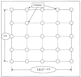
Figure 1. Plane View of Scaled Flat Slab (Symmetric Spans).
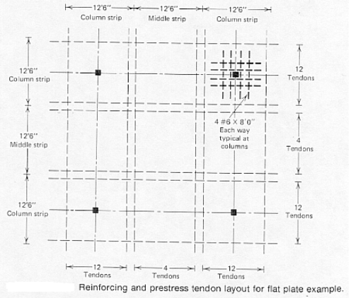
Figure 2. Reinforcement and Tendon Layout of Scaled Flat Plate Slab.
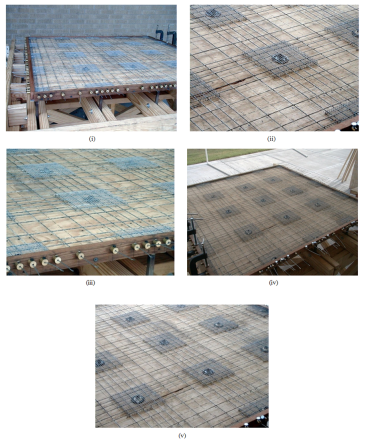
Figure 3. Exploded View of Formwork and Reinforcement Layout of Flat Plate Slab.
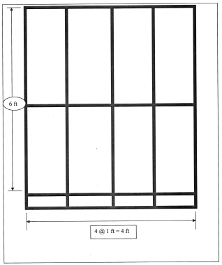
Figure 4. Plan View of Water Tank.
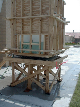
Figure 5. Experimental setup showing water tank on the scaled flat plate slab.

